Inventor Sheet Metal Partial Flange

Solved Sheet Metal Flange Only On Partial Edge Autodesk Community Inventor

Flange Feature In Inventor 2015 Youtube

Cat Volvo And More Mega Crazy Construction Machines Bucket Drawing Excavator Buckets Technical Drawing

Belt Chain For Conveyor In Solidworks Youtube Solidworks Conveyor Videos Tutorial

Autodesk Inventor Sheet Metal Tutorial Basics Youtube

Inventor Sheet Metal Folds Youtube

Optional if a body exists click new solid to create a new body.
Inventor sheet metal partial flange.

Pin Em Solidworks

Pin On Solidworks Catia Ansys

Solved Control Flange Length Autodesk Community Inventor

Creating A Chamfer On A Sheet Metal Part Youtube
Autodesk Inventor Sheet Metal Drawing Tutorial Basics Youtube Sheet Metal Drawing Drawing Tutorial Autodesk Inventor

About Flanges In Sheet Metal Inventor 2018 Autodesk Knowledge Network

Solidworks Tutorial Using The Jog Feature Lynda Com Youtube

Sheet Metal Design Siemens Solid Edge Tutorial Youtube

Forged Steel Bellow Gate Valve 800lb Dn20 Sw End Gate Valve Forged Steel Valve

Quick Tip Mastering The 3 Types Of Draft In Inventor Youtube

Creo Sheetmetal Tutorial How To Create Flange Wall Feature Youtube

Fusion 360 Sheetmetal Youtube

To Rip Sheet Metal Features Inventor 2018 Autodesk Knowledge Network

Pin By Noe On Machine Autocad Isometric Drawing Mechanical Engineering Design Solidworks Tutorial

Hexbolt Bluezincplatedhexbolts Carbonsteelbearinglockhexbolts Coldheadinghexbolts Customedtitaniumhexbolts Heavydutyhexbolts Highstren Hex Bolt Bolt Hex

Video Tip Fusion 360 Sheet Metal Flat Pattern And Unfold Youtube

Diseno De Un Tanque Con Solidworks Youtube Disenos De Unas Tanques Tutoriales

Ejercicios De Solidworks Panosundaki Pin
Https Encrypted Tbn0 Gstatic Com Images Q Tbn 3aand9gcsslkmd24fnut8oay5u6ncpsfkj Zddtna M7ndjrzpbynt Pb2 Usqp Cau

Applying Fillets To Corners In Inventor Youtube

Autodesk Inventor How To Split Parts Using Surfaces Youtube
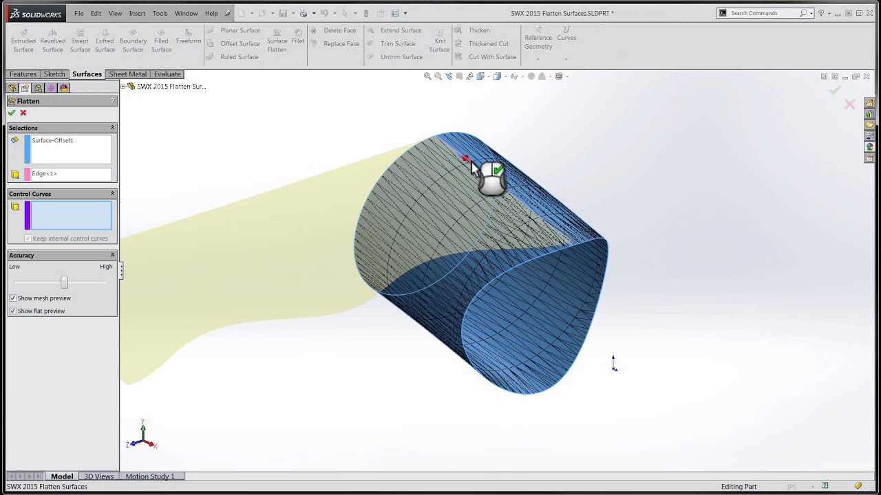
Tech Tip Solidworks 2015 Tutorial Flattening Surfaces Youtube
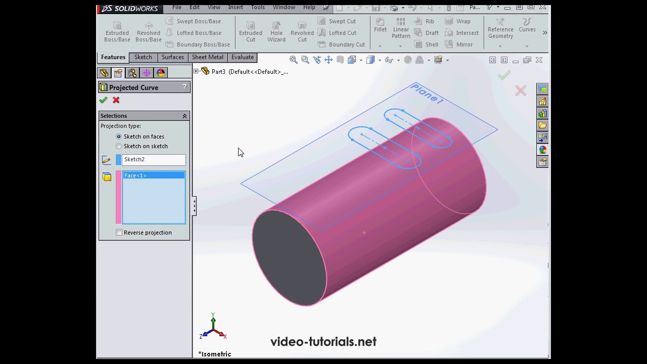
Slots On A Cylindrical Surface Solidworks Tutorials Q A Youtube

Pin En Arte Renacentista
Source : pinterest.com
